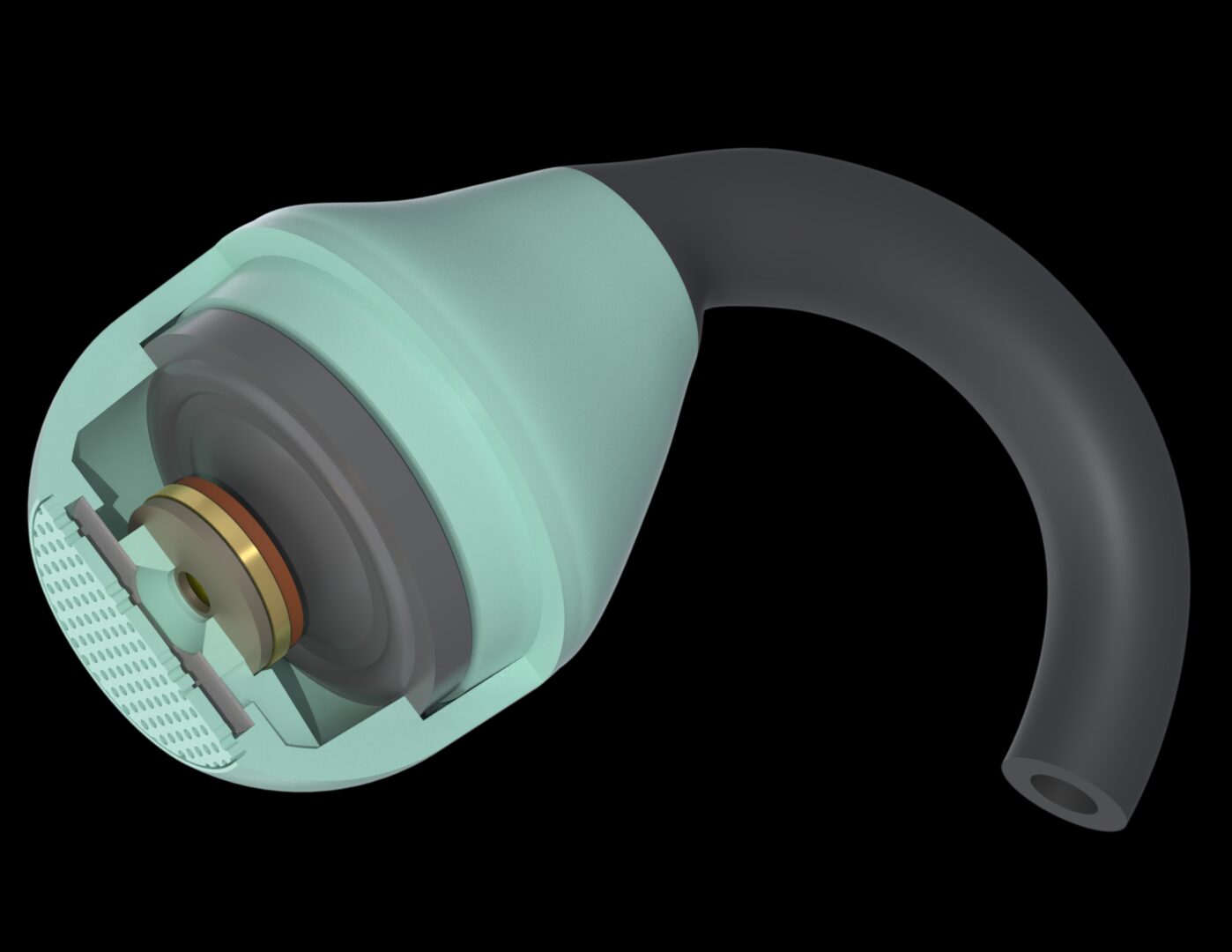
Open Wireless Stereo (OWS) earphones are becoming increasingly popular as an alternative to conventional in-ear headphones. This article is intended to serve as an overview of how to integrate a high-end two-way loudspeaker system into a typical OWS form factor.
Why Use a Two-way Architecture for an OWS Earphone?
Due to the unsealed, open-ear nature of an OWS system, achieving strong bass output is challenging. This requirement becomes even more demanding when headroom must be reserved for active noise cancellation (ANC). As a result, asking a single driver to generate the required low-frequency excursion while simultaneously reproducing high frequencies up to the upper end of the audible spectrum can lead to difficult design compromises.
Dividing the audio spectrum into two bands allows the two drivers (woofer and tweeter) as well as the surrounding acoustic design to be optimized for their respective frequency ranges. In addition, intermodulation distortion caused by the large diaphragm excursions required for low-frequency output can be significantly reduced.
Basic Layout
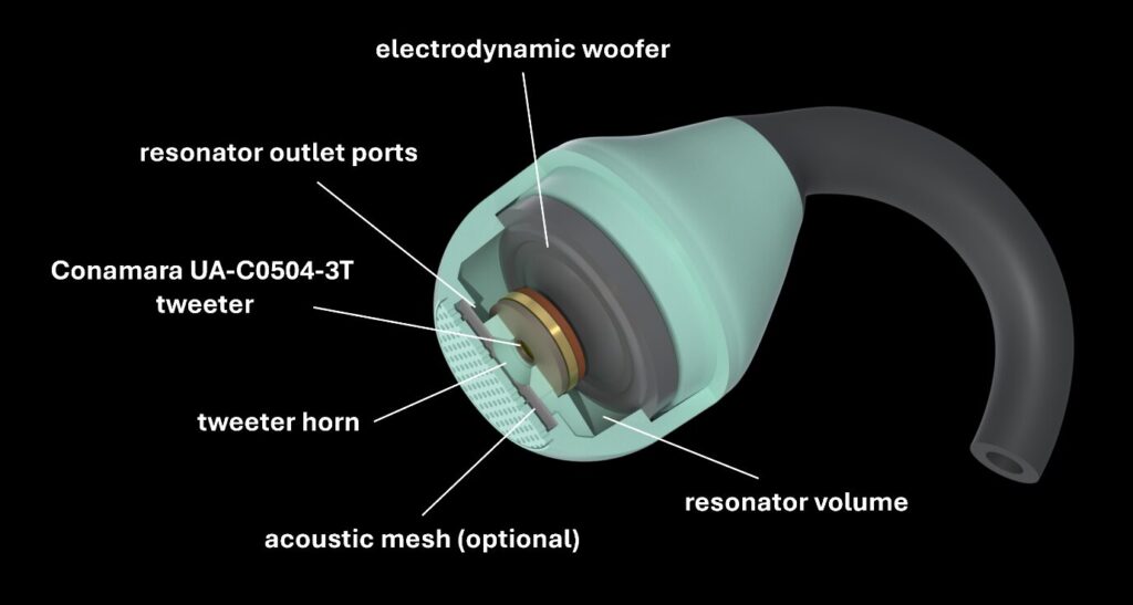
For compact packaging, the woofer and tweeter should be positioned one behind the other. As high-frequency sound waves are, simply put, more easily obstructed, the tweeter should be placed as close to the ear entrance as possible. Low-frequency sound, by contrast, can diffract around objects that are small relative to its wavelength, allowing the woofer to be positioned behind the tweeter. Sufficient clearance needs to be provided to allow for the woofer’s maximum diaphragm excursion. The result is a layout like the one shown below.
Acoustic Tuning
Positioning the two speakers as described inevitably creates a Helmholtz resonator, formed by a) the air volume between the woofer and tweeter and b) the small outlet ports on the woofer at the front. It is advisable to tune this Helmholtz resonance frequency in relation to the tweeter’s resonance frequency. Two basic cases can be distinguished:
Case 1:
The resonator’s outlet ports act as reflex ports, similar to a bass reflex port, common in subwoofers and other speaker enclosures. In the frequency range between the two resonance frequencies, the outputs from the front and rear sides of the tweeter diaphragm are in phase, leading to a significant increase in SPL and thereby extending the tweeter’s usable range below its resonance frequency.
At the same time, the resonator acts as a resonant acoustic low-pass filter for the woofer. The tweeter, on the other hand, being subject to an acoustic short circuit (below), exhibits high-pass behavior. In conjunction, a natural acoustic crossover is achieved.
Case 2:
This tuning can be used to boost a specific frequency range above. With the resonator ports acoustically open below, the resulting acoustic short circuit attenuates the tweeter’s output. The degree of this attenuation can be adjusted by applying an acoustic mesh on the resonator ports. Note that this mesh also affects the woofer response around its resonance frequency.
It can be preferable to tune to sit only slightly above; the overlapping resonance peaks form a plateau, and the SPL drop caused by the acoustic short circuit is well compensated for by the tweeter’s resonance peak.
Measurement Results
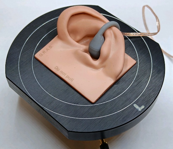
Now, let’s take a look at concrete measurement results, obtained using an IEC 60318-4 (“711”) ear simulator fitted with a KB5000 pinna simulator by GRAS. As the measured response of an OWS earphone is sensitive to its position relative to the pinna, multiple measurements should be taken at slightly different positions; the median SPL at each frequency point can then be used to calculate a representative response.
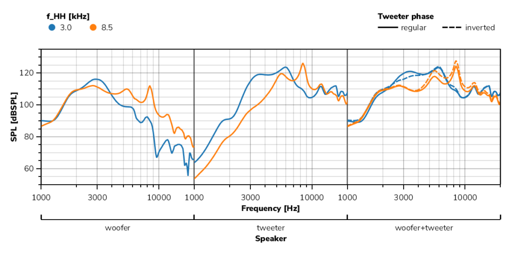
The results below were obtained using the same basic OWS design but with two different acoustic tunings, as described above. For the measurements, USound’s ultra-thin Conamara UA-C0504-3T tweeter was combined with a woofer typical of this application.
Observations:
- Both the woofer and the tweeter exhibit an SPL boost at the Helmholtz resonance.
- The woofer output is attenuated above the (low-pass behavior caused by playing through the resonator).
- The tweeter output is attenuated below (due to the acoustic short circuit).
- Depending on the resonator tuning, inverting the tweeter’s phase can reduce destructive interference between the woofer and the tweeter.
Conclusion
When using Conamara UA-C0504-3T with its resonance frequency of 5 kHz as a tweeter in a two-way OWS system, the following two practical recommendations can be derived:
- Want to get the most out of the two drivers and focus on the frequency range most relevant to speech intelligibility and perceived loudness? Then tune to be around 2–5 kHz. Consider using an acoustic mesh to reduce attenuation of the tweeter output below its resonant frequency.
- Want to create a flatter woofer-plus-tweeter frequency response and/or boost a specific frequency range above? Tune accordingly and invert the tweeter’s electrical polarity.
Interested in a more in-depth analysis and further insights? Our engineers are available to support your development with reference designs and acoustic tuning advice tailored to your specific requirements.

About the author
Christian Bachleitner-Hofmann is an Acoustic Engineer at USound. Having initially graduated from Vienna University of Technology in Mechanical Engineering, he brings extensive product development experience and now focuses on acoustic simulation, testing, and prototype development.